|
CHAPTERS |
INTRODUCTION
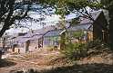
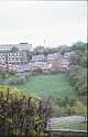
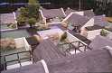
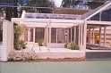
Work on site began in June 1983. Initially it was expected to take 18 months to complete the project, but at the present stage it appears the final time will be closer to 3 years! After completion a Residents' Association composed of the householders will supervise and develop the shared aspects of the site, such as the demonstration building and the common garden area at the north of the site. Three basic house types were developed, namely, a three bedroomed semi detached, a semi detached starter home and a single storey court house, all offering scope for variation and extension. All materials and labour skills are traditional to the building industry. The houses have a timber frame internal construction, with brick and blockwork insulated cavity outer walls, tiled roofs and timber and glass conservatory. Construction was designed carefully to make things straightforward for self builders. This project has a number of unusual and interesting aspects; its solar and low energy designs, its self build approach, the cooperative organisation and the low-cost building implications. The following report aims to describe the project generally and give information on each of these aspects in more detail and in relation to the project. |
|
.jpg)
.jpg)
|
|
DESIGN,
CONSTRUCTION & THERMAL ASPECTS |
|
.jpg)

|
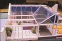
THE
HOUSE DESIGNS The
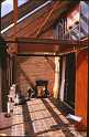
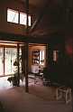
L-shaped conservatory was a response to the site orientation, and
the plan which evolved placed the bathroom and utility space as
a services core in the angle of the house not benefiting directly
from solar gain, and provided a courtyard outside on to which the
conservatory opened. Initially,
the Coop project was envisaged as consisting of a cluster of these
L-shaped or courtyard houses. Various factors led to the development
of additional designs. The
accommodation in the courtyard house was large enough for a family,
and this was reflected in its cost. It seemed appropriate to develop
a cheaper starter-home alternative, with possibilities for later
expansion. This idea was increasingly attractive, as it offered
scope for a higher density of site development and therefore lower
individual costs for shared services. In addition to these factors,
the site considered by the Coop was fairly steeply sloping in places
and not suitable in
these places for the L-shaped design. The
Coop members were anxious to have semi-detached houses rather than
terraced houses, and so the design developed was for pairs of semis
with a continuous roof. Taking account of the slope of the site,
each pair would consist of a three bedroomed, two storey house,
with the possibility of future extension into the roof space and
staggered in relation to this, a single storey house further up
the slope, which was a true 'starter home' but could be extended
upwards to provide bedrooms in the roof space later. The
eventual site arrangement includes five L-shaped houses and four
pairs of semis. In fact, only the first pair of semis was built,
with one side as a starter home, as thereafter the Coop members
who were having starter homes found they could afford the extra
money and opted for
the extra space in the larger side of the semi, and so the final
three pairs of houses have staggered roofs and handed plans. The
L-shaped house plan is set out on a 640mm grid, which is determined
by the 610mm square horticultural glass panes used in the vertical
glazing of the conservatory. The structural centres are at 2560
mm with four grid units to each structural bay. The
roof trusses are supported at 2560mm centres on posts at the division
between house and conservatory and on the external walls of the
house. The
double row of posts between the house and conservatory support deep
double beams which provide lateral stability and a services duct.
The four posts at the centre of the house provide the corners of
the central air duct through which air is drawn from the high level
ducts along the top of the conservatory down into the hypocaust. The
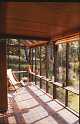
post and beam construction between the living area is closed with
glazed doors on winter days with the addition of insulated shutters
on winter nights. This 'wall' between the heated space of the house
and the conservatory can be opened up completely to provide a continuous
living space in the summer - the glazed doors are hinged and fold
back against the posts and the shutters can be re-positioned to
form a ceiling in the conservatory which gives summer shading to
prevent overheating. In certain cases patio doors have been put
in instead of folding glazed doors, but these do not allow full
opening of the space between living area and conservatory. In
order that the habitable rooms open on to the conservatory, it is
preferable to locate the kitchen and bathroom in the services 'core'
in the square of the house not opening on to the conservatory. The
entrance of the house is also integrated on to this side of the
house, leaving the conservatory aspect of the house with privacy. The
basic house type plan consisted of three structural bays in each
direction. The internal layout is very flexible, and the differing
requirements and preferences of the five Coop members having these
houses have given rise to five very different houses within the
same basic structure. In some cases, full or half bays have been
added or omitted from one wing of the house, to increase or reduce
the size. The
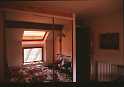
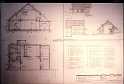
rooms which open on to the conservatory have high sloping ceilings,
as can be seen from the section, whilst the ceilings in the services
core are horizontal at 2.3m high. In some bedrooms galleries have
been extended into the room, with their floors supported on the
truss ties, to take advantage of the high ceiling space. Usually
use has been made of the area above a flat ceiling for storage areas. The
accompanying plans show the variations which have developed. The
last of these houses to be built was varied in that the central
rows of posts were placed slightly further apart, in order to accommodate
a door between them. This is typical of the continual modifications
and evolution of design in response of individual needs which has
been part of the project. In certain cases this has produced results
which are a long way from the original intentions, but the low-energy
aspects of the design have remained intact. The
semi-detached houses have certain principles and design features
in common with the L-shaped houses. The ratio of conservatory area
to house floor area is much smaller however. The associated reduction
of potential solar collection is counteracted by the compact nature
of the accommodation which leads to lower heat losses. In
the three-bedroomed houses the kitchen, bathroom and staircase are
located on the northerly side of the house, which cuts into the
hillside. The living room can be opened to the conservatory to provide
a continuous space in summer, using the same system of folding doors
and shutters as is found in the L-shaped houses. In
the starter home, the initial accommodation is provided on the ground
floor, with the kitchen and bathroom on the north side at the 'back'
of the house. The utility room or study is also located on this
side of the house; this latter being the space into which the stair
will be fitted at a later date. The living room and bedroom areas
open on to the conservatory. The accommodation provided here is
minimal, but ideal for a single person or couple, who wish to take
advantage of lower rates whilst having the option of expanding their
accommodation later without the expense and inconvenience of moving
house. The
starter home can be 'expanded' by making use of the roof space to
provide up to three bedrooms, and inserting the dogleg stair in
the downstairs utility or study area. The
section of the starter home differs from that of the three bedroom
semi. The starter home is essentially a single storey house with
room for expansion in the roof space whereas the three bedroom semi
is a two storey house with room for expansion in the attic. The
attic space in the starter home, however, has much more headroom.
The structural section and trusses used for each of these house
types are different, although they are designed to have a common
roof ridge. The two house types interlock beneath the common ridge,
the starter home being staggered backwards
and having a higher ground floor level, making this pair of houses
ideally fitted to the slope of the site. Again
these houses are built relating to a one directional grid of 640mm
which relates to the glass size of the horticultural panes used.
The roof lights in the sloping ceilings of the bedrooms relate to
this grid; the roof truss and double posts are also positioned on
this grid. The scope for individual plan variation is less in these houses than in the L-shaped houses, but again individual requirements have resulted in differences and innovation. The most marked of these is the planned extension forward of one conservatory which will result in a double height and double depth conservatory. |
|
.jpg)
.jpg)
.jpg)

.jpg)
|
|
"MOYA"
- House for Mr and Mrs C Oldham - Charsfield, Suffolk "Moya", the house for which the original design concept was developed, was in fact built by a local Suffolk builder in the summer of 1984, whilst the Coop project was on site and provided further opportunity for design variation and development. Because of the close links with the Coop project it seemed appropriate to include details of "Moya". |
 |
|
HOUSE
CONSTRUCTION The
construction of the Coop houses is a hybrid of load bearing brickwork
and timber framing. The main variation in construction is between
the semi detached, two storey houses and the L-shaped single storey
houses. Further variations arise from the different gradients encountered
on various parts of the site, and from the desire of the Coop members
to experiment with different techniques and solutions to problems
as work progressed. The
reason for the hybrid construction was to take advantage of the
speed of construction associated with the erection of a timber frame
which had been pre-fabricated on site. The masonry walls provide
much of the thermal mass which provides a large amount of the heat
storage in the building and these also provide support for the timber
frame once they are constructed. The
following paragraphs will outline the construction of the various
building elements and highlight variations in these. The general
annotated cross-section of the type 2 building will illustrate their
relationship and the specification clauses will give further detail. Foundations The
footings are concrete strip foundations below walls, stepped where
necessary. The posts of the timber frame have pad foundations. Where
there is a concrete sub-slab to the floor this has been thickened
for blockwork partitions. Retaining
Walls The
slope of the site, which is very steep in places, meant that many
of the external walls of the houses are retaining walls. The construction
of retaining walls is obviously less straight-forward and more expensive
than simple external walls and they did provide the self builders
with problems, especially at first. Various
methods of construction of retaining walls were tried, in order
to try to overcome the practical difficulties of continuity of the
damp proof membrane. What looks fairly simple on section often becomes
very complex when it becomes three-dimensional. The
height of earth retained was limited to a metre wherever possible
and the variation of construction were:- The
floor construction With
the exception of the 6 houses at the top of the site the ground
floor construction of the houses is a hypocaust construction, through
which warm air from the conservatory is blown by a fan, and the
hypocaust acts as a heat store. The mechanics and theory of this
is explained more fully in the section on the thermal system. Every
hypocaust has a 100mm concrete sub-slab on hardcore, sand blinding
and damp proof membrane. This sub slab was laid before the external
walls were built above ground level and edge insulation of styrofoam
was included below it. The
hypocaust construction was usually completed once the shell of the
house was completed. In the first two houses this was constructed
of bricks on edge which were arranged in spaced rows to support
sheets of corrugated tin or plastic on to which concrete was poured
to give a 100mm thick slab. A screed finish was put on top of the
slab later. In
certain L-shaped houses the slope of the site meant that the fill
below the sub slab in the floor bays at the extreme south western
end of the house was going to be excessive, so in such cases end
bays had precast concrete beam suspended floors, with insulation
below. Generally,
the floors in the conservatories are simply tiled concrete slabs,
but in one house the hypocaust construction has been taken right
through into the conservatory, with under slab insulation. An
important element in the hypocaust construction for the functioning
of the thermal system is the provision of gaps and grills to return
the air from the hypocaust extremities to the onservatory. Also
important is the arrangement of the bricks in order to direct the
air moving through the hypocaust so that air will go to all parts
of the hypocaust and will not short circuit and return to the conservatory
before it has given up its heat to the hypocaust structure. Whereas
in the houses on the lower part of the site the bays with suspended
concrete floors are isolated from the main hypocaust construction,
in the six houses at the top of the site the whole upper hypocaust
floor is actually formed from precast concrete beams. The
slope of the site in this area meant that the original hypocaust
construction was not feasible. Here the cavity between the site
concrete placed on the ground and the suspended concrete floor form
the hypocaust cavity into which warm air from the conservatory is
blown. The
Timber Frame As
can be seen from the sections, the timber frame is much more extensive
in the one storey house design than in the semi detached houses,
although in both cases the timber elements are all cut and drilled
according to detailed timber schedules, and lists of elements leads
to great speed in frame construction. Considering
the single storey house first, the timber frame is prefabricated
initially. Once frame construction begins the frame can usually
be erected in a weekend on top of the sub slab of the floor. The
frame is supported by a series of temporary posts which support
the frame until the external walls are built. The frame is squared,
levelled and anchored and then provides the setting out for the
external walls which are built up to the frame. In later houses
the backs of the trusses were supported on a wall plate and the
temporary posts removed and used on the next house. The
advantage of this method is that the roofing felt can be put on
immediately the frame is secured, the external walls can be built
up and the temporary supporting posts can be removed once the walls
have been built to support the frame. The roof can be tiled immediately,
the conservatory glazed and the whole building envelope can be completed
in a smooth, fast operation. With
the semi detached houses, the timber elements are pre-fabricated
and integrated and fixed as the external walls are built. Here
there are variations on the number of trusses used. This particular
self-build group is short of people confident in carpentry skills,
and so in some cases, instead of having a truss and boarding on
the gable walls, brickwork load bearing gable walls have been taken
to roof level. Axonometric
views show the timber frame construction. Internal
Partitions Initially,
all the internal partitions were designed to be stud partitions,
for ease of construction and later flexibility. Coop members, again
due to a lack of carpenters, found blockwork construction preferable,
although this entailed thickening of the floor slab below partitions
and obstruction of the hypocaust in places. Blockwork partitions
were also preferred due to their increased sound insulating properties.
Insulation The
external walls were constructed of an outer skin of brickwork, a
75mm cavity, 100mm inner skin of insulating 'Thermalite' blockwork
with foam cavity fill insulation injected after construction. The
floor was insulated with 1m wide 50mm thick styrofoam edge insulation.
In the
semis the first floor ceiling joists were 125mm deep and insulation
was put in here in addition to between the 125mm roof rafters. Where
the attic space was not going to be used immediately, extra insulation
was included above the first floor ceilings. Generally 200mm of
fibreglass insulation was used, in between the joists. In
the single storey houses, where the ceilings sloped, separate ceiling
joists were positioned below the roof joists to allow for at least
200mm of insulation and to give space for ventilation, over the
insulation. Where
the ceilings are flat 200mm insulation is included between the ceiling
joists. The
shutters provide winter insulation between the houses and their
conservatories. The
Shutters The
shutters are constructed from plywood glued to a simple timber framing
with a 25mm polystyrene insulating core. They were made on site
initially, but later were subcontracted. They
are situated on the outside of the doors between the living and
the conservatory areas. They are designed to be closed on winter
evenings, and are intended to be moved to make a horizontal ceiling
in the conservatory to provide summer shading. Various methods of
fixing and shutter operation have been devised, depending on the
preferences of individual house owners. The original concept was
to have four shutters to each bay, hinged in pairs from the structural
posts for winter use, and hinged to swing upwards from the beams
for summer shading. This system utilises hinges with removable pins. Different
methods of shutter fixing adopted include simple sliding shutters,
which are more easy to operate with patio doors. The
Conservatories The
detailing of the conservatories is in keeping with the original
design philosophy of the houses; they are designed to be simple
to build, and to be glazed with horticultural glass to keep costs
low. In fact, regulation changes meant that the roofs of the conservatories
are glazed with 4mm float glass or toughened glass rather than with
horticultural glass. For safety, where toughened glass was not used,
an inner pane of polycarbonate or acrylic was specified, fixed with
beads under the sloping glazing. The
grid of the whole house is a 640mm grid, with larger bays of four
grid units. This grid size originates from the horticultural glass
which comes in 610mm panes. The
conservatory frame is built of simple planed timbers, and the glazing
is carried out as indicated in the details, with a putty-free method
which makes glass installation much quicker and easier. Instead
of using rebated timbers, stops are planted on each vertical glazing
bar. The glass is bedded on a pvc covered foam strip and held in
place by parting beads pinned to the stops. On the roof glazing
beruing strips are screwed to the glazing bar, holding the glass
down on the pvc covered foam strip. Variations
on these details have been used in practice, depending on personal
taste. At
the base of each vertical glass window a kick panel of pvc is fixed
for safety. The
Spandrell Panel Collector The
spandrell panel solar collector is constructed with a black painted
ply panel, with insulation between the panel and the inside of the
house. The glazing of the panel is fixed with beads using horticultural
glass to the same detail as in the conservatory. In
certain cases where rooms have a high ceiling in the single storey
houses, the spandrell collector begins higher up, the area below
it being glazed to let light into the room above the shelf over
the double beams. |
|
.jpg)
.jpg)

.jpg)
.jpg)
.jpg)
.jpg)


|
|
SUMMARY-
LOW ENERGY & SOLAR FEATURES 1.
The buildings are orientated to maximise solar gain and arranged
to avoid overshadowing each other. 2.
High insulation levels in roof and walls to conserve energy. 3.
Small windows on the 'dark' northern side of the house; windows
are double glazed. 4.
Economical planning of the heated area of the house. 5.
Large amount of thermal mass in the building structure. 6.
Control of ventilation and condensation using conservatory and lobby
as buffer zones. 7.
Weather stripping to all door and window openings. 8.
Conservatory as passive solar collector of direct and diffuse radiation. 9.
Spandrell panel solar collector inside conservatory. 10.
South facing double glazed doors opening on to conservatory to maximise
direct solar gain in 'heated area' of house. 11.
Fan assisted transfer of solar heated air from collector to heat
store. 12.
Hypocaust floor heat store. 13.
Bread box water heater. 14.
Insulating night shutters. 15.
Use of planting and hinged shutters to give summer shading to conservatory. 16.
North side of house dug into slope, with additional earth berming
for shelter and insulation. |
|
|
|
THE
USE OF SCRIBE ON THE CO-OP PROJECT In
June 1983, when the Coop Project started on site, SCRIBE was at
the stage of being primarily a three dimensional and thermal modelling
program. Although development work had been taking place on SCRIBE
for three years previously, the version of the program at that time
was limited when compared to its present capabilities. In
the summer of 1983 a range of plotters came on to the market at
a price which for the first time was compatible with the rest of
the hardware equipment used with SCRIBE. This meant that further
development of the SCRIBE system for draughting purposes was now
worthwhile. Work
on enhancements for SCRIBE was fairly intensive for the next year,
using work and drawings for the Coop scheme to test, give feedback
and often instigate the various improvements to the program. The
way SCRIBE was used throughout the Coop scheme reflects this developmental
role. The techniques which we used towards the end of the project
were the result not only of experimentation with and integration
of microcomputers into the architects' office, but also of the increased
capabilities of the program. Bearing
this in mind, the description below outlines how SCRIBE was actually
used on the Coop project, and describes the final methods which
were adopted, after both program enhancements and experience. At
the site planning stage of the Coop scheme, SCRIBE was used intensively
as a design tool, giving instant projects and perspectives of various
site arrangements from all angles. This was useful, not only from
the design aspect, but it also helped the Coop members and prospective
members to know what to expect. It made them much more familiar
with the site and the project at a stage when most laymen would
find it difficult to visualise more than the site as a field! SCRIBE
was also used at this early stage to determine the layout of the
houses in such a way as to maximise the solar gains and to reduce
shading on the solar collectors (here the conservatories). A quick
run through of the SOLPRO module with the three dimensional model
of the site showed where the sun would reach at every hour through
the day for any chosen day in the year. This provided a quick, but
essential, check that shading had been minimised in such a solar
scheme. SCRIBE
was also used to do thermal analysis of the house designs. The more
simple steady-state heat loss calculation module was used to give
an early estimate of radiator sizes and boiler output requirement.
The dynamic thermal modelling calculations (SPIEL) were more important,
as they provided forecasts of the total environmental performance
of each house design, and the heating costs. This program allowed
cost benefit comparisons to be made for increased insulation and
the use of different construction materials. The results also gave
the opportunity of checking for problems, such as cold areas, interstitial
condensation, and gave information on the predicted way the hypocaust
would work, such predictions being based on figures rather than
intuition. The
three dimensional models of each house type generated for these
thermal calculations were also used to give interior and exterior
views of the houses. At
the stage when the house plans were being drawn, early in the project,
SCRIBE had not been developed fully enough to be used for such finished
drawings, and dimensioning was also a later enhancement. This was
regrettable as the Coop scheme represents a housing scheme to which
SCRIBE is well
suited. A number of similar houses with variations is ideal for
gaining maximum benefit from such a system. Once the basic plan
has been put in amendments can easily be made to the model and a
lot of repetitive drawing time can be saved. SCRIBE
was used for most of the Co-op details, where a library of details
was built up over the period of the project, and amended and developed
as necessary. Such a method involves similar time to drawing by
hand when the details and element libraries are first being created,
and also a good system of organisation so that information stored
is easy to find again. Thereafter, it will save a lot of time. As
we used SCRIBE in the office, we were determined to use the system
to save drawing time where we could and to enable us to do analysis
which, if done by hand would not be feasible. We found that by using
SCRIBE the initial design ideas and possibilities could be explored
more thoroughly, especially the three dimensional implications at
an early stage. The whole aim was to use the computer system to
best advantage, rather than being pedantic and trying to use the
computer for everything. There are certain things that people do
much better than computers, and where this was the case we admitted
it. Thus,
the drawing techniques we developed were hybrid techniques. Finished
perspective drawings and sketches are done using the SCRIBE output
as a skeleton to trace over. The most successful view to take for
a perspective can be explored exhaustively just using the computer
model. Hatching
and shading are usually done by hand on drawings. Notes are often
added using the word processor, and printing on to transtext, as
this is quicker for larger blocks than using the text module in
SCRIBE. The
drawings are done using an A3 plotter because as yet (1981) the
larger plotters are still disproportionately more expensive. If
larger drawings are needed, we put all the necessary information
to a smaller scale on an A3 sheet and enlarge to A1 by photocopying,
a process which is now accurate whilst giving good results. |
|


|
|
COOPERATIVE
ASPECTS The
way in which Sheffield Solar Building Coop was to be run was determined
at a very early stage in the project, by the small group of people
initially involved. Monthly Cooperative meetings were held from
a very early stage. |
|
|
|
WORK
ORGANISATION The
organisation of the project was based on the Coop members working
together, initially on two houses. As each house was completed it
was to be sold to its owner, and work on the next house could begin.
In this way the Coop could limit the amount of money it needed to
borrow at any one time. In practice, work was often in progress
on more than two houses at a time, because it was more practical
and economical to excavate and put in foundations of a number of
houses together in the dry weather. The main object was project
planning to ensure that it was always possible to complete and sell
the next house in progression, whilst remaining within the loan
limit. At the same time, it was important to ensure that there was
always indoor work to be done during the bad weather. How this worked
can be seen in the chapter outlining the site diary. Each
building member of the Coop was required to work on the project
for a certain number of hours each week. The required number of
hours varied from 20 to 30 hours, depending on the size of house
that person was having. The working of hours was operated in a flexible
way, and any person having done less hours than they should have
done over a six month period was required to pay the Coop for the
hours they had not worked. This amount was paid in cash, worked
out on an hourly rate. Once
a person's house was completed to a 'habitable shell' standard it
was sold to them. The house price included the site cost, an amount
for shared road and service installations and the cost of materials.
A refundable premium of £2,000 was also added to make sure
that they did not stop working until all the houses were completed!
The costs involved are outlined in the chapter on finance. |
|
.jpg)
|
LOW
COST FEATURES OF DESIGNS Comment |